cuRobo generates motions for a robot to reach a target pose under geometric and robot constraints. It takes a robot model, a description of the environment and a start state, and returns a planned trajectory for a separate controller to execute. The cuRobo and cuRoboV2 publications describe different planner designs.
How can one obstacle change a joint trajectory?
- InputSpecify the problem
start joints + target pose + world geometryFix the target and choose which obstacles to include.
- ProcessOptimize a motion
kinematics + collision checks → waypointsFind joint states that reach the goal and clear the obstacle.
- OutputVerify in saved data
motion.npz · result.jsonRead the planned joints separately from tool-center coordinates.
From tool pose to joint trajectory
The target is a tool position and orientation. Control runs through a sequence of joint values. Robot kinematics maps those values to the tool and link positions. cuRobo searches for intermediate joint states that reach the target without colliding with the specified geometry.
Read the effect of adding an obstacle
The recorded example adds a 4 × 4 × 8 cm box. The baseline has 24 waypoints and the replanned trajectory has 26. The three columns of obstacle_tool in motion.npz are tool XYZ. obstacle_q holds the joint values for that trajectory. The lab checks whether sampled tool positions enter the box, while the planner also uses the arm’s link geometry. Planner source · cuRobo repository · Robot motion lab
Architecture and data flow
| Component | Inputs, processing and outputs |
|---|---|
| Robot and collision geometry | Kinematics describe the joints and links. Collision geometry approximates the robot and models obstacles in the world frame used by the planner. |
| Inverse kinematics and trajectory optimization | For a Cartesian goal, inverse kinematics generates candidate joint goals. The original planner evaluates and refines candidate trajectories on the GPU, taking collision and motion costs into account. |
| cuRoboV2 | The V2 publication describes torque-aware B-spline optimization, GPU-native depth-fused distance fields and whole-body kinematics and dynamics. Check which API and collision backends your installed version exposes. |
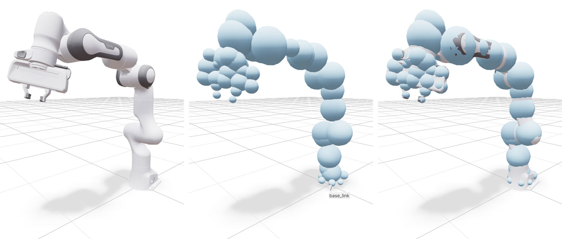
The Franka illustration shows the link-attached collision spheres used for planning. Check whether the approximations cover the actual links, gripper and any held object. Official figure source

The cuRoboV2-Fast deployment figure connects scene perception, grasp proposal and torque-limited motion planning. The object surface and the collision-distance map take different paths through the system. Official paper, figure 17
Worked example
- For a pick-and-place transit, provide the current joint state, target tool pose and obstacles in a common frame. Inspect the planned trajectory in simulation first.
- Pass the accepted trajectory to the controller and check tracking and clearance separately. Replan if the scene changes.
What to verify
- Check orientation conventions, joint names and collision margins. Incomplete collision geometry can produce a path that is clear only in the model.
- Read the planner status and benchmark the workload on the target GPU. Planning latency and physical controller tracking measure separate stages.
Official references and terms
The repository code uses Apache-2.0. Review LICENSE_ASSETS and component terms when using robot assets or integrations.
- Repository and version-specific releases
- Original cuRobo paper
- cuRoboV2 architecture and evaluation
- Current cuRobo documentation and release notes